TAP System Overview
What is all this stuff?
Introduction
The TAP System is a collection of Pre-made and fully tested modules for use in high end audio pre-amplifiers. Used together these modules create a remote controlled preamplifier system with sonics at the very peak of what is capable. The modules all use the highest quality parts and feature extremely short and optimized signal paths. These parts can combine into a full featured passive pre-amp or alternately can be used to form the 'shell' of a fully remote controlled active preamplifier. The TAP System Modules are used by some of high end audio's finest preamplifier manufactures and are also available for DIY projects of all kinds.
Selecting TAP System Parts
To put together a TAP System simply choose a front panel pcb, attenuator modules, a power supply pcb, Bent Metal remote control handset, and optionally, an input select pcb. These modules then easily plug together with the included ribbon cable. All that is left is to wire up the signal path wiring - the modular nature of the system makes this wiring easy and clean.
Below are some design notes about these various choices:
A Front Panel PCB or Module
- Full Width Front Panel PCB
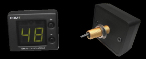
- The PRM-1 mounted inside the metal PRM-1 Enclosure
- A Naked PRM-1 pcb
- A Custom Front Panel pcb to meet exactly your design requirements
There are 4 front panel choices:
The Full Width Front panel is usually only an option if you are using the AVC-1 enclosure for your diy build or if you are an OEM builder making your own enclosures. The 'locked in' placement of the buttons and leds on this pcb make it a difficult enclosure project for a typical diy builder.
The PRM-1 (Pot Replacement Module) in it's own enclosure is the easiest to implement - requiring only a single hole in the front panel for mounting. This makes a DIY enclosure build very easy. It also makes retrofitting TAP system modules into existing preamplifiers possible without front panel machining - often the PRM-1 will fit in place of the existing attenuator using the same mounting hole.
For OEM customers (or advanced DIY enclosure builders) wanting to keep the front panel design simple and clean, the PRM-1 pcb can be placed just behind the front panel. Click HERE to see an example of just such an enclosure.
The last option is a custom designed front panel. Please keep in mind such projects are seldom cost effective until we reach 50 to 100 piece quantities. Below that quantity the cost per pcb becomes unreasonable . . .
All these front panel pcb choices control all of the TAP System attenuator and Input Selection Modules. The only difference is the user interface; no functions are lost when choosing the smaller PRM-1 module. Most often the choice of which front panel suits your system pretty much makes itself.
Attenuator Modules
- The Slagleformer Module
- Hybrid Resistor Module
- Hardwired TVC PCB
There are 3 choices of Attenuator Modules:
The Slagleformer Module our finest level control device. It takes the extreme audio quality of Dave Slagles Autoformer level control and packages it up in a system allowing full remote control volume with a small 1db step size from -54db up to +7db. The nature of the autoformer construction makes for very tight unit to unit matching and the way autoformers treat impedances make these ideal for both fully passive and active pre-amp designs. If you can afford the price then Slagleformers are the way to go.
When your budget rules out the Slagleformers then the Hybrid Resistor Module is a great choice. It features a very short clean signal path and the same small 1db step size as the Slagleformer - giving a range from -60db up to unity gain. Two impedance options are available (10K and 50K). Although they are admittedly a notch below the Slagleformers sonically these modules appear in OEM pre-amps up into the $15K range - some pretty nice sounding gear! Also these make a great option when retrofitting a remote system into existing gear where the size of the Slagleformers make them impossible to fit into the enclosure
For DIY and OEM customers wanting to make use of TVC's on hand or for those who have a favourite TVC supplier this pcb will do the job nicely. The Hardwired TVC PCB allows connection of up to 32 TVC taps. We set the front panel you choose to the matching number of steps prior to shipping. This PCB also includes relay selection for up to 6 inputs, a mute relay, and a spare relay to use for other functions. Two TVC PCBs are used for a typical stereo project.
All these options allow for right/left balance control and Mute via remote control. Connect up as many Attenuator Modules as are needed via the supplied ribbon cable. A basic 2 channel pre-amp will use 2 modules and a fully balanced stereo pre-amp will use 4 modules. Most often a system will use one of these attenuator types for all channels but they can be mixed if that suits the application. An example of that would be when using Slagleformers for front channels while at the same time using Hybrid Modules (to save cost) for the rear channels in a multichannel system.
Optional Source Selection Modules
If you would like to include source selection via remote control in your product then simply add a source selection module to the system. Like the front panel pcb, this is also a choice that pretty much makes itself - Your requirements (RCA/XLR, etc) will point you to the module to use.
- RCA Hardwired PCB
- RCA PCB with Jacks
- XLR Hardwired PCB
- XLR PCB with jacks
There are 4 choices of Input Selection Module:
Choose the RCA Harwired PCB if you have up to 6 RCA inputs using your own RCA jacks. This PCB also has a mute relay and a spare relay for implementing other functions.
Choose the RCA PCB with Jacks if building a project into the AVC-1 Slagleformer Enclosure or if you are an OEM (or advanced DIY builder) making your own enclosures using automated machinery. Since the RCA jacks are pre-mounted to the PCB it 'locks in' the back panel cutout making it difficult to do with hand tools. RCA jacks include 6 inputs and dual outputs plus a tape out rca jack. One pcb handles both the right and left channels.
Choose the XLR Hardwired PCB if you require up to 6 XLR inputs. This PCB includes full switching for both left and right channels. Also included is a full alternate set of input switching with pin2 and pin3 swapped for those applications that allow phase inversion. This novel layout accomplishes that phase inversion while introducing NO additional contacts into the signal path. Some single ended RCA connections can be included in the mix as long as the mating circuits are setup to handle them. Like the other PCB options it includes a mute relay for both the left and right channels and a spare relay for special applications.
Choose the XLR PCB with jacks if, as an OEM (or advanced DIY builder), you are making your own enclosures using automated machinery. Like the RCA board with connectors, it is very difficult to DIY build the enclosure to mate up with the pre mounted XLR jacks. One PCB is used per channel and each PCB includes 6 XLR inputs plus 2 XLR outs and a switched XLR tape output. A Mute relay is also installed.
Power Supply PCB Choices
Every TAP System must include a power supply pcb. Some notes on these are listed below.
- Hardwired Power Supply
- Back Panel Power PCB
There are 2 choices :
This small PCB can be tucked away anywhere inside your enclosure. Feed it 9Vdc and it regulates that power down to the 5Vdc required by the TAP System Modules. It then routes that power onto the included ribbon cable. If using the PRM-1 Front Panel module then this is the PCB designed to mate with it. For systems using the Full Width front panel pcb this is also the option to choose if you are feeding the system power from a built in power supply.
This power pcb is designed to be mounted at the back panel of the enclosure and to have DC power fed directly into the pre-amp via the small DC power jack at the back panel. The connectors mounted this pcb require an accurate back panel cutout so it only makes sense as a choice when using the AVC-1 Slagleformer Enclosure or if as an OEM (or advanced DIY builder) you are making enclosures using automated machinery. This PCB is fed 9Vdc power via a small 2.1mm (center positive) power jack. The 9Vdc power is then regulated down to 5Vdc and routed onto the included system ribbon cable.
Remote Control Handset Choice
Every TAP System uses a remote control handset. This is the easiest choice - there is only one handset that operates all the functions - the 13 button Bent Metal Handset. This handset allows the user to adjust the following functions via remote control:
- Volume Up and Down
- Balance Right and Left
- Mute
- Direct Input Selection (1-6)
- Display On/Off (for dark mode listening)
- Misc relay funtion (for tape or phase typically)
Please e-mail or call with any TAP system configuration questions. I'm happy to work with customers to be certain they end up with the very best solution to fit each project.
OEM / DIY TAP System Modules Manual